Spartan-6 Microboard: 16-bit R-2R DAC! [Part One]

So how do you produce a usable, somewhat analog signal out of a purely digital device? Well it’s actually simple; use a R-2R ladder and a bunch of digital pins. Basically we’re turning a dearth of extremely high speed digital IO pins into one high-resolution analog output. Oh, also necessary for this circuit (go ahead and crack out the protoboard and soldering iron) is 3 matched resistor per bit of resolution; so in our case, 48.

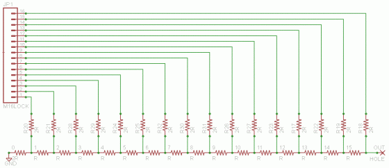
A 16-bit R-2R Ladder Schematic

A 16-bit R-2R Ladder Schematic

Fun! Here’s a diagram. So how’s it work? When we drive our 16 outputs with digital logic, each pin has half the voltage range of its leftwards neighbor — due to it being a stacked  voltage divider. This is exactly how you  convert from binary to decimal; each digit has twice the value of one neighbor, and half that of the other (discounting the Most and Least Significant Bits) so we can  convert 1s and 0s into a wide numeric  range of values.

This is probably confusing: I know how it works, and I just confused myself. For a *much* better explanation, refer to this previous post of mine.

We’ve got a  circuit, we know conceptually how it works, how do we make it do? Make…make it do right? This is where my brain started screeching to a halt. Hell, I must be driving with the E-brake on, because this is actually super easy, and explaining why helps to understand VHDL/Verilog.

Firstly, in programming languages, things happen sequentially: A, then B, then conditionally C, for example. In Hardware Description Languages, things happen simultaneously: A <= a and B <= b and C <= c all happen simultaneously. Secondly, all of our analog values we’d want to output, such as 62101 is actually represented in a variable, described thusly:

wire [15:0] our_var

It’s actual designation in the chip is in the form 0b1111001010010101.
This means all we have to do to convert our digital data to our analog output at full clock speed is this:

always @(*) begin
pin15 <= our_var[15]
pin14 <= our_var[14]
...
pin1 <= our_var[1]
pin0 <= our_var[0]
end

These all update at the same time, and our output is produced thusly. So, I’ve been dismissing the most major disadvantage? Speed. Lets say we want to make a 16b sine wave. Our speed is limited to f_clk/number_of_levels. So FM is out of the question with this particular implementation (I’m not ruling it out completely, let me know if you know more than I do) but it’s the perfect speed for audio applications.

With a 350MHz DCM, and using 16,384 distinct levels, I can generate a f_max of around 21kHz, well above the range of human hearing. So let me work on getting that code finished, and I’ll return tomorrow. I’ve got my wheels pointed towards the curb, and my E-brake on, and I need a break for the night.
Spartan-6 Microboard: FM All-Band CQ Transmitter

Here we go! This time we’re starting something a little bit more advanced. Lets check out the digital clock manager (DCM), which allows us to make custom clocks that run faster or slower than the actual physical clock. So what are we going to do with this? We’re going to make an FM transmitter that can transmit on any amateur radio band* and, of course, the standard FM radio band.

* please note this is totally illegal if you’re not a licensed HAM. So if you get caught, that’s on you.

I got most of this code from hamsterworks. It was a short simple piece of code that would type out S O S on 91MHz. I made it slightly less ridiculous I having a type out CQ (this is used to seek out contacts.) At least that way, my neighbors aren’t taking an axe to their dashboards trying to find a little man screaming for help. My neighbors are weird like that.

I put a ~1M long piece of 22Ga wire in the output pin, and get at least 10M range. No idea what kind of power I’m putting out (microWatts at most) and I fixed the frequency drift by finding the exact frequency given by the DCM.

Since this code had to be modified (only slightly, I won’t lie) I did some of my best commenting; I know that would have helped me. (Mind the scrollbar at the bottom.)

FM_Xmit.VHD

library IEEE;
use IEEE.STD_LOGIC_1164.ALL;
use IEEE.NUMERIC_STD.ALL;

entity fm_xmit is
    Port ( clk : in  STD_LOGIC;
           antenna : out  STD_LOGIC;
	   rst : in STD_LOGIC;
	   sw : in std_logic_vector(3 downto 0)	
	   );
end fm_xmit;

architecture Behavioral of fm_xmit is
   component fast_clock
   port ( CLK_IN1  : in  std_logic; --These are the signals from our Digital Clock Manager
          CLK_OUT1 : out std_logic; --Make sure the names are the exact same (not case sensitive)
	  RESET    : in std_logic   --Or this won't work at all
   );
   end component;

   signal clk320            : std_logic;
   signal shift_ctr         : unsigned (4 downto 0) := (others => '0');
   signal phase_accumulator : unsigned (31 downto 0) := (others => '0');
   signal beep_counter      : unsigned (19 downto 0):= (others => '0'); -- gives a 305Hz beep signal
   signal message           : std_logic_vector(33 downto 0) := "1110101110100001110111010111000000"; --gives CQ in morse

	signal band_160m			: std_logic_vector (3 downto 0) := "1111"; --These are the 
	signal band_80m				: std_logic_vector (3 downto 0) := "1110"; --positions of 
	signal band_60m				: std_logic_vector (3 downto 0) := "1101"; --the 4 onboard
	signal band_40m				: std_logic_vector (3 downto 0) := "1100"; --dip switches,
	signal band_30m				: std_logic_vector (3 downto 0) := "1011"; --giving us a
	signal band_20m				: std_logic_vector (3 downto 0) := "1010"; --binary band 
	signal band_17m				: std_logic_vector (3 downto 0) := "1001"; --select.
	signal band_15m				: std_logic_vector (3 downto 0) := "1000";
	signal band_12m				: std_logic_vector (3 downto 0) := "0111";
	signal band_10m				: std_logic_vector (3 downto 0) := "0110";
	signal band_6m				: std_logic_vector (3 downto 0) := "0101";
	signal band_2m				: std_logic_vector (3 downto 0) := "0100";
	signal band_1_25m			: std_logic_vector (3 downto 0) := "0011";
	signal band_fm				: std_logic_vector (3 downto 0) := "0000";
	shared VARIABLE upper_side_signal: 	INTEGER; --these variables allow us to calculate
	shared VARIABLE lower_side_signal: 	INTEGER; --our clock divider ratio from the base 
	shared VARIABLE current_freq: 		INTEGER; --320MHZ (319996800Hz) to get our square
	shared VARIABLE center_signal: 		INTEGER; --wave period right

begin

clock320 : fast_clock PORT MAP(
clk_in1 => CLK,
clk_out1 => CLK320,
reset => rst
);

   antenna <= std_logic(phase_accumulator(31));

   process(clk320, sw)
   begin
	IF    (sw = band_160m) 		THEN 	current_freq := 1810000; --these are the standard morse
	ELSIF (sw = band_80m) 		THEN 	current_freq := 3560000; --calling frequencies in the USA
	ELSIF (sw = band_60m) 		THEN 	current_freq := 5403500; --modify them to whatever you like
	ELSIF (sw = band_40m) 		THEN 	current_freq := 7040000; --in Hz.
	ELSIF (sw = band_30m) 		THEN	current_freq := 10106000;
	ELSIF (sw = band_20m) 		THEN 	current_freq := 14060000;
	ELSIF (sw = band_17m) 		THEN 	current_freq := 18080000;
	ELSIF (sw = band_15m) 		THEN 	current_freq := 21060000;
	ELSIF (sw = band_12m) 		THEN 	current_freq := 24910000;
	ELSIF (sw = band_10m) 		THEN 	current_freq := 28060000;
	ELSIF (sw = band_6m) 		THEN 	current_freq := 50090000;
	ELSIF (sw = band_2m) 		THEN 	current_freq := 144100000;
	ELSIF (sw = band_1_25m) 	THEN 	current_freq := 222100000;
	ELSIF (sw = band_fm) 		THEN 	current_freq := 100100000; --100.1 MHz, open freq here
	ELSE         
    current_freq := 91000000;
	END IF;

	upper_side_signal := (current_freq/319996800*(2**32)) + 75000; --This exact clock frequency fixes
	lower_side_signal := (current_freq/319996800*(2**32)) - 75000; --the 'drift' shown in the video
	center_signal := (current_freq/31996800*(2**32));

      if rising_edge(clk320) then
         if beep_counter = x"FFFFF" then
            if shift_ctr = "00000" then
               message <= message(0) & message(33 downto 1);
            end if;
            shift_ctr <= shift_ctr + 1;
         end if;      

         if message(0) = '1' then
            if beep_counter(19) = '1' then
               phase_accumulator <= phase_accumulator + upper_side_signal; --+75kHz signal               
            else
               phase_accumulator <= phase_accumulator + lower_side_signal; -- -75kHz signal
            end if;
         else 
            phase_accumulator <= phase_accumulator + center_signal; -- center frequency signal
         end if;

         beep_counter <= beep_counter+1;
      end if;
   end process;
end Behavioral;

Pins.UCF

NET "clk" LOC = C10;
NET "antenna" LOC = F15;
NET "rst" LOC = V4;
NET "sw[0]" LOC = B3 | PULLDOWN;
NET "sw[1]" LOC = A3 | PULLDOWN;
NET "sw[2]" LOC = B4 | PULLDOWN;
NET "sw[3]" LOC = A4 | PULLDOWN;

Spartan-6 Microboard: Firing It Up!

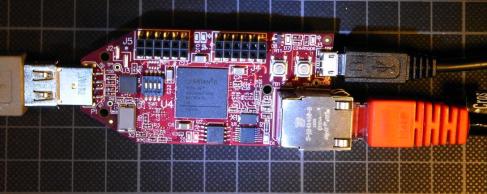
S6 Microboard powered via USB Mintyboost

S6Microboard powered via USB Mintyboost

I promised this article 4 days ago. I apologize. I’ve made it worth it.

Getting this project running was a bit of a beast. Not the development or implementation, those are based on public code, previously tested on this device. No, the trouble was in figuring out exactly how to program/load this board, driver issues, and how to code for this board. That is all now figured out.

I started by finding this set of articles by this Duane Benson fellow (they are topically listed at the bottom). He gives good, fairlyunderstandable instruction, but some aspects are just plain incorrect. In one article, he explains how you must use exclusively the micro-USB for programming, when in reality, you must use the full size USB port.

You will need the CP210x driver, but don’t bother trying to get it from Avnet’s malignant tumor of a website. Download it directly from Silicon Labs. (by the way, the CP210x series chips are extremely interesting, they have a USB-to-I2S adapter I’d like to experiment with…) Once you have the drivers squared away, plug it in, we’re cookin’ with gas now!

Okay, so how do you actually get information into the board: enter Matthew Galloway, or his site at least. This is what you need, and pretty much everything you need to get this thing blinking: his Blinkenlights tutorial. You’ll also want to download a copy (me not trusting the site) of the S6Microboard Manual which gives the names of the physical locations on the board.

Got blinkenlights? Good. Now were ready for the next project: tomorrow.

I promise.

Discovering FPGAs Series by Duane Benson:

*This is not yet a complete listing of this series, and this series is continuing

What’s This All About?
Opening the Package
Sorting Out the Pins
Flashing the LEDs
More About the UCF
Adding LEDs & Modifying the Verilog
Bringing Up the IDE
Creating the .BIT File
Loading the .BIT File
Playing With LEDs & Switches
Adding in the Switches
Driving a 7-Segment Display
The ChipScope Virtual Logic Analyzer
Alternative Latching Strategies
Getting to Grips With ChipScope
Observing Switch Bounce With ChipScope
Modules in Modules
Creating a Logic Analyzer
Selecting a Syntax
Building a Two-Stage Synchronizer
My Logic Analyzer Takes Shape
Debugging a Motor Driver
Becoming a Clock Wizard
I See Clocks Everywhere!

Update: Spartan-6 LX9 Microboard

Image

I’ve gotten this development board in, and it is amazing! Haven’t had time to do much but plug it in and watch the example design blink away at me, but impressive knowing instead of a microprocessor controlling the pattern, it’s an actual (mostly) physical multivibrator circuit (I’m assuming, or a binary counter (i think in this case that’d still apply (woo nested parenthesis (it’s late, forgive me.))))

Where-was-I-going-with-this that’s right.

Xilinx/Avnet support for this product is abysmal to the point of embarrassment. That’s a bit harsh. I believe they’ve simply let their respective websites become spaghetti coded to shit, making the documentation, drivers, and reference designs become deadlocked behind levels and levels of infinite loops of server redirects. I’ve contacted them, but in the mean time, I’ve found an excellent listing of tutorials (for both this product, and FPGAs in general) that I will me manually sorting and posting, tomorrow evening, round this time.

Stay posted, let me know what your thinking down below.

I’m out.

Teaser: Spartan-6 LX9 Microboard

Sparta-6 LX9 Microboard from AVNET and Xilinx

Sparta-6 LX9 Microboard from AVNET and Xilinx

This is teasing you as much as it is me. This is the Microboard. it’s an FPGA development board with onboard ram, 10/100 ethernet, and USB (among the various blinky switchy things all development boards must have) for the low, low cost of around $90.

Or if you know someone like Vlad a bit cheaper. Thanks for the donation!

For my first project, I’m looking at a simple FM (re)transmitter.  I want to make a local area delay filter. Think about it.

A better, faster, stronger DAC: An R-2R Ladder!

This is amazing. In this video, he simultaneously explains the concept of making Thevenin equivalent circuits (handy!) and shows the (actually pretty simple) mathematics behind this circuit. This method basically allows you to trade many digital pins and many resistors for a single, excellent analog out. B-E-A-utiful.

Planning on using this on an FPGA for an absolutely stupid-ridiculous resolution analog stream. Why not? I’ve got 36 conductor ribbon cable and 108 matched resistors that would be better served as a 36-bit analog out.

That actually might bring me closer to implementing HDMI…naaahh.

Mojo Spartan-6 FPGA Boards!

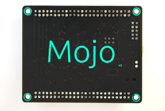
Mojo Back

Mojo Spartan-6 FPGA Boards!

I’m not gonna lie, super excited for this project. I’ve been wanting to get started with FPGAs for a while now, but the price was too high. Not to mention, you have to learn a new language, or two (VHDL and Verilog, you had better learn both eventually.)

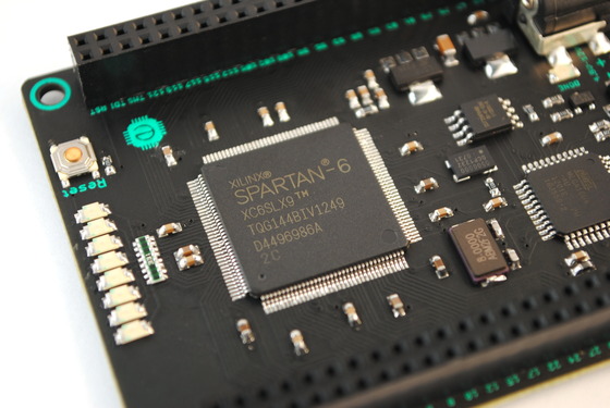
Spartan-6 Chip; ATMega16u4 Far Right

The Mojo board simplifies it, or will attempt to. Coming in at only $74.99, the price is quite right; and the creators aim to step you through tutorials as they roll out the project. Now, compared to most FPGA development boards, it doesn’t have many bells and whistles: no Ethernet, VGA, HDMI, USB Host, high speed RAM, or much really. It gets by with just a reset button and 8 leds, if you really want it, you can just wire it up (except the high speed ram, that requires additional engineering, shipping from Krypton; that involves Superman — don’t even bother.)

Anyway…was saying…excited!

Check out this list of premade modules (called cores) while we wait, and spam the hell out of them till they sell you one — you won’t regret it!

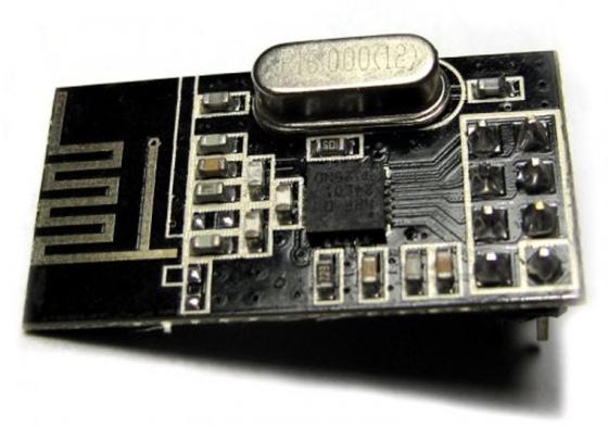
nRF24L01+ Module Documentation

nRF24L01+

Library

Arduino Library Download
Copy to ‘Libraries’ folder within your main Arduino folder.

Pins:

MISO -> 12
MOSI -> 11
SCK -> 13

Configurable:

CE -> 8
CSN -> 7

Properties:

byte cePin
CE Pin controls RX / TX, default 8.

byte csnPin
CSN Pin (Chip select not), default 7.

byte channel
RF Channel 0 – 127 or 0 – 84 in the US, default 0.

byte payload
Size in bytes, default 16, max 32.
Note: channel and payload must be the same for all nodes.

Methods:

void init(void)
Initialize the module, set the pin modes for the configurable pins and initialize the SPI module.
Example:
Mirf.csnPin = 9;
Mirf.cePin = 7;
Mirf.init();
void setRADDR(byte *addr)
Set the receiving address. Addresses are 5 bytes long.
Example:
Mirf.setRADDR((byte *)"addr1");
void setTADDR(byte *addr)
Set the sending address.
Example:
Mirf.setTADDR((byte *)"addr1");
void config(void)
Set channel and payload width. Power up in RX mode and flush RX fifo.
Example:
Mirf.payload = 32;
Mirf.channel = 2;
Mirf.config();
bool dataReady(void)
Is there data ready to be received?.
Example:
if(Mirf.dataReady()){
//Get the data to play with.
}
void getData(byte *data)
Get the received data. 'data' should be an array of bytes Mirf.payload long.
Example:
byte data[Mirf.payload]
Mirf.getData(data);
void send(byte *data)
Send data. 'data' should be Mirf.payload bytes long.
bool isSending(void)
Return true if still trying to send. If the chip is still in transmit mode then this method will return the chip to receive mode.
Example:
Mirf.send(data);
while(Mirf.isSending()){
//Wait.
}
//Chip is now in receive mode.
NB: Lots more information is available from the status registers regarding acknowledgement or failure status. See Mirf.cpp:218.
bool rxFifoEmpty(void)
Is the RX Fifo Empty.
bool txFifoEmpty(void)
Is the TX Fifo Empty.
byte getStatus(void)
Return the status register.
void powerUpRx(void)
Power up chip and set to receive mode. Also clear sending interrupts.
void powerUpTx(void)
Power up tx mode.
Exa

Examples

See examples folder in zip file.
Arduino Library Download

I’m attempting to replicate this project, and hopefully, I’ll turn it into a neat little software-defined radio for 2m, 1.25m, and 70cm. We shall see shortly.

Building A Thermostat Using Arduino

This gives an excellent description of the technique. I’ve still yet to determine the switching current, which I’d like to before I build a potentially hazardous item. End goal of this project? Constructing a ‘Nest’-like learning thermostat. Mostly just to predict when I’ll come stomping in from the cold, and adjust the temperature appropriately an hour or two ahead of schedule.

Keeps it toasty.

Create a free website or blog at WordPress.com.